I recently started a new job as a board designer. In my second week into the post, I stumbled into something I wasn’t prepared to see on a multi-thousand dollar board… A 5V external signal is coming into the main PCB and needs to communicate with an input that only accepts 3.3V. As I inspect the schematic, I’m trying to find the level shifter but can only see two resistances doing a voltage divider before going inside the input. I could not believe it. Wouldn’t this mess up the signal integrity of the transmission line? Also, I couldn’t imagine this was the only solution the principal designer found to shift 2 common voltages. So asked my supervisor why they went on the cheapest route instead of using a level shifter. He just smiled at me and said: “There aren’t a lot of level shifters available that are radiation resistant. Anyways, the communication speed is very slow and the input impedance is high so it shouldn’t pose any problem.”
With those wise words in mind, I present you with 5 ways to interface 2 chips with different voltage requirements! But first, I have a question for you :
Why do we need a way to interface in and out when working with different voltage?
This seems obvious but the answer isn’t actually this straight foward as 3.3V out pin can’t drive a 5V in pin and vice versa. In some cases, as we’ll see later, we may be lucky enough to not need any type of translator.
But let’s say we are in the unlucky scenario, what can happen? In the case of a low-voltage pin trying to drive a higher-voltage pin, probably nothing… The input will see a constant 0 as if it was tied to the ground.
In the case of a higher voltage output driving a lower voltage input, well, there are risk of destroying the input and probably more if you’re not careful.
Using a good old level shifter
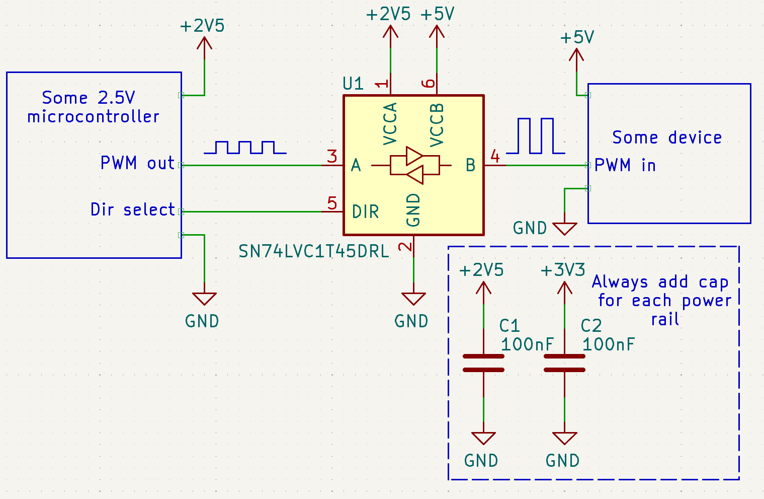
To simplify nomenclature let’s say you have a microcontroller that runs on 2.5V (let’s call it voltage VA), and you want to use a pwm on a device that needs 5V (Voltage VB).
Whenever you need to switch from one voltage to another, the level shifter should be your go-to. They are super easy to use, can reach great speed, and cost pennies. You can also find them by the name translator. There are a lot of different types of level shifters available, but today I’ll discuss only the 3 fundamental ones that you will most likely use: unidirectional, bidirectional, and open drain.
The operation mode is simple. Apply VA on VCCA of the level shifter and VB on VCCB. You can now communicate with 2 different voltages without worrying about frying your pin! If your level shifter is bidirectional, it either has auto sense technology or a pin called “dir” will be provided with a truth table in the datasheet that will let you switch the side which is the out or in. In the unidirectional case, A is always the “in” (receives the logic level) and B the “out” (translates the logic level).
An image will explain one thousand times better what I’m trying to explain to you. So take some time to explore the little diagram under here where I use a SN74LVC1T45 chip. This is a pretty common bidirectional level shifter that in this case, is driving a PWM signal and claims to be able to attains some pretty decent speeds (420 Mbps when translating from 3.3V to 5V)!


In some cases, when you don’t want a logic 1 to be coming from the level shifter but from a pull-up, like when using I2C, the previous chip isn’t the wise choice. I would instead use an open drain level shifter. This way I can have as many devices as I want on every single end of the shifter without worrying about who’s the input or the output. The way of operation is easy, both ends are tied to their own “1” logic level with their respective pull-up resistor. Whenever a device needs to pull the line down, both lines go down at the same time. Look at this ready to use TXS0102, it even includes the resistors!

Making a voltage devider with series resistances
What about the case I’ve encoutered previously? The voltage divider is a bit trickier to pull of because you have to do some maths and only works one way, from higher voltage to lower voltage.
\[V_{out} = V_{in} * \frac{R_2}{R_1 + R_2}\]Doing a bit more math, we can isolate R1 or R2 :
\[R_1 = \frac{V_{in}-V_{out}}{V_{out}} * R_2 \quad \textrm{or} \quad R_2 = \frac{V_{out}}{V_{in}-V_{out}} * R_1\]Knowing Vout and Vin, we can select a standard 1% resistor for R1 or R2 and solve for the other one. Of course, since we are finding the second resistor with algebra, we won’t find a second 1% standard value. Just choose the nearest higher value for R1 or lower for R2. This will ensure that Vout is lower than what you desired and won’t destroy your input pin with too much voltage.

Now, this trick may cost cheaper than a level shifter but it has its limits… Every controller has an input and output impedance, and this may deteriorate the quality of the signal to a point that the receiver can’t properly differentiate logic level anymore. I may write an article about this (Soon™). Just keep in mind that with a transmission speed over 250KHz, I wouldn’t risk a PCB to save 25 cents.
When doing this method, they are some other considerations that need to be taken in account. You have to make sure to not push more than the current limit per pin of your driving IC and its VOH/VOL. For the receiver IC, you have to look at the VIH/VIL.

Take this ATmega328P microcontroller for example. When run at 5V the minimum output high voltage (VOH) is 4.1V and maximum ouput low voltage 0.8V. The maximum current that the output can drive is 20mA sustained.


On the other hand, the receiver chip, for instance this M95P16-I SPI EEPROM will see a logic a between 0.75*VCC and VCC+0.6 where VCC is generally 3.3V or whatever is supplied on the VCC pin of that chip.
So, when you are designing your voltage divider, you must make sure that all these constraints are respected. The last image is the best visual representation I could make to summarize the concept.

Not doing anything (WARNING can destroy your input pin)
All the theory explained in the earlier section is still valid here. This is why mixing technologies is often harder than anticipated. If you truly want to do this, make sure to read both datasheets of the ICs that you want to connect together and make sure that the VOH and VOL will work with the given VIH and VIL.
If the input pin voltage is lower than the output, say a 3.3V pin is driven by a 5V pin, BE SURE that the input clearly states that it is 5V tolerant and connect a series resistor on the line. 22 ohms is a common value for this, but use anything that is in the ballpark of 100 ohms that is already in your BOM.
Using a MOSFET
Transistors are amazing, they can do so many things that the Microelectronics Circuits manual, a book that is over 1000 pages long, just scratches the surface of what transistors can do. But here, we’ll simply use an N-channel MOSFET, a very commonly used type of transistor, as a level shifter.
The way the MOSFET is used here can be compared to a GPIO controlled switch. For the driver side, add a series resistor (typically 10 ohms) to the GPIO and the gate. Then just put a pull-up resistor at the drain and connect the same drain to the driven device. Et voilà! You can now drive your input at basically any voltage you want! (Provided that the MOSFET VDS can support it.)

There are some caveats, though. First, the logic will be inverted. Second, the speed won’t be great (typically under 1 MHz) because of the whole physical characteristics of a MOSFET. Last, the required voltage will depend on a characteristic called Vth. This can be found in every MOSFET datasheet and will dictate the minimum voltage required to enter the triode mode that will make the MOSFET act as a switch in our case. In theory it is a little more complicated than that, but a good rule of thumb is that small MOSFETs can be driven by 1.8V microcontrollers or more, and bigger ones will require higher voltage, like 3.3V. This is a huge simplification, but it is enough for the purpose of the article.
Side note here: you cannot swap the place between the MOSFET and the resistance in a way that the resistance becomes a pull-down to revert the signal back. If you want to know why, there is plenty of information available online for this.
Overall, MOSFETs and other types of transistors can be used as level shifters, but they have other strengths and have higher potential elsewhere.
Using an Optocoupler
If you have to communicate between two boards and they don’t share the same ground, or perhaps you want to isolate two sections of your board, your search ends here. Meet the optocoupler! Again, this component can do so much more than just flipping high voltage to low voltage, but for the purpose I am describing today, we’ll keep things easy. In a nutshell, you simply have to turn on a LED that will trigger a transistor on the other side of the IC. Pretty easy, but there is one thing to keep in mind. You are turning on a BJT type of transistor, which means that it is controlled by current. This current is decided by how bright the LED will emit from the transmitter side.

Let’s take a look at the LTV-356T optocoupler datasheet. There are a couple of important points that can’t be ignored. It’s not just applying voltage to the LED then the transistor will magically turn on and off. On the input side, you must notice that the LED will drop your voltage by 1.4V. This means that this is the minimum required voltage to even just turn on the optocoupler. Then there is the most important parameter, IF , which is the current going through that LED. This parameter paired with the current transfer ratio (CTR) will dictate how much current can go through the transistor before it stops acting like a dumb on and off switch (going out of saturation). The best way to remedy that problem is to follow the minimal CTR of 50%, which means that if you send 5mA in the LED, the transistor can guarantee a minimum of 2.5mA of passthrough. Of course you can also study the graphs on the datasheet and get better CTR. But in the end we generally try to consume the least amount of current when it comes to transmitting data. The following formula will give you a way to decide your resistors choice for the circuit :
\[\frac{V_{in}-1.4V}{R_1} = I_{in} \quad \textrm{|} \quad (V_2-0.2V) * I_{out} = R_2\]
Conclusion
This article was supposed to present 7 ways to level shift. But I decided to cut the part using a comparator and relay because it was more for giggles than serious ways to do things. If you have other ideas on how to interface two ICs, please share them with us with a comment down below!